
Power factor correction. Consider a 750kVA load operating at 80% lagging PF. Construct a power triangle to help determine the kW and kVAR components of the power (Fig. 1A above).
Solving for the real and reactive power values yields 600kW and 450kVAR, respectively.
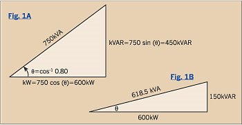 So of the 750kVA drawn from the source, only 600kW, or 80% of it, can do useful work. The reactive power, necessary to establish electromagnetic fields, adds a considerable burden to the source.
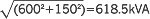
Last month's column showed that capacitors connected from line-to-neutral can furnish reactive power. With a 300kVAR shunt capacitor, the source has to provide only 150kVAR (450-300=150). Fig. 1B shows the resulting power triangle.
The kVA supplied by the source decreases to
and the PF angle θ decreases to
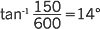
yielding a new power factor of cos 14°, or 97% lagging.
This process of installing shunt capacitors to supply reactive power is called power factor correction.
Efficiency.
Efficiency is the ratio of the energy output of an appliance to the energy input, expressed as a percentage. Since appliances require more energy than they provide, some energy is lost. But where does it go?
Depending on the type of appliance, energy can “escape” in a number of places. Electrical losses (I2R) usually account for a significant portion of the total losses, producing heat in the appliance. Iron-core devices exhibit hysteresis losses, which are magnetic losses in the iron, and eddy current losses, which are electrical losses in the iron core. Induction motors and transformers display a significant leakage reactance, which are the losses due to inductance. As the harmonic content of the current increases, skin effect losses increase greatly in the conductors. Rotating machines have rotational losses due to bearing friction and rotor windage.
Although many appliances are designed for maximum efficiency, losses will never be eliminated.