Newton's Law of Viscosity gives the relationship between the shear stress and the shear rate or the velocity gradient of a liquid that is subject to a mechanical force.

The law is not universal in its application.  It is applicable to some liquids while other liquids do not obey it.

Newton's Law of Viscosity can be mathematically described as

t =  m dv/dy

where t = shear stress
           dv/dy is the velocity gradient

Liquids which obey Newton's Law of Viscosity are called Newtonian liquids.  Liquids whose response cannot be described by this law are called Non-Newtonian Liquids.


A Newtonian liquid is one in which the viscosity of the liquid is constant regardless of the stress applied.  That is, the viscosity of the liquid is the same if it is left alone or agitated vigorously.

In other words, Newtonian liquids obey Newton's law of viscosity which states that the shear stress is proportional to the rate of strain.

Water is a common example of a Newtonian liquid.  The viscosity of water is same whether it is still or in an agitated state.  In contrast, a solution of water and corn starch will be liquid when still but will become highly viscous when agitated.

Liquids in which the viscosity changes in response to the application of stress are called non-Newtonian liquids.


Rheology is the science of the flow of matter, particularly in the liquid or the semisolid state.  It is a subject of interest when designing pumps.  Rheology can help describe the behaviour of materials such as slurries and pastes.

The term Rheology is formed from two Greek works, "Rheo" for flow and "logia" for study. It is based on the assumption that "everything flows" or "Panta Rei", a statement attributed to Heraclitus, a philosopher in ancient Greece.Rheology can also be described as the study of the behaviour of matter when subject to  a deforming load.

In Rheology, flow is considered to be an irreversible deformation of matter as the original state of the fluid or the semi-solid cannot be attained again.

Rheology has applications in the food industry, in pharmaceuticals and in chemical industries.


Peristaltic pumps work by pushing a fluid through a tube.  The liquid is moved in a tube due to the formation of constrictions.  The impeller of the pump consists of two wheels which press against the tube and move the constrictions and the liquid.

The advantage of this pump is that the medium does not come in contact with the impeller.  Hence, this pump is widely used in the field of medicine.  Many life support systems use this pump as they handle body fluids such as blood.

Peristaltic pumps are also used in the food industry where the purity of the food is to be maintained.


Metering pumps are special pumps which are used to deliver a liquid at a specific flow rate in a specific time.  Metering pumps are used for dosing chemicals in industrial processes at a specific quantity.

The quantity and duration is often controlled by a computer.

Metering pumps are positive displacement pumps which can deliver output at high pressures. The pump is usually driven by a piston.

For sensitive liquids which require sterility and for corrosive liquids, the pump is ideal as it does not come in contact with the liquid.  A diaphragm acts as the interface between the piston and the liquid.

Metering pumps can also be designed as gear pumps.


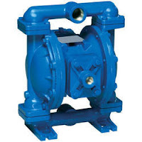
A diaphragm is a special type of pump which uses a diaphragm to create pressure.  The diaphragm pump consists of a container with an inlet and outlet valves.  The top of the container is covered with the diaphragm.

The diaphragm is operated by an external mechanism which moves the diaphragm up and down.  When the diaphragm is pulled up, low pressure is created and the liquid is drawn inside the pump.  When diaphragm is pushed down, the fluid inside is pressurized and released through the outlet valve.


A salient feature of the diaphragm pump is that the fluid does not come in contact with the pump components.  Diaphragm pumps are used in the field of medicine where they can be used to construct artificial hearts and in dialysis.

They are also used widely in the food processing industry.

Another common application is in aquariums.  Aquarium pumps which provide air to aerate aquariums are a type of diaphragm pumps.


Plunger Pumps and Piston pumps work on the same principle.  They both draw a fixed volume of liquid through the inlet and pressurize the liquid and then release the liquid.

The difference lies in the construction.  In Piston pumps, the seal which prevents leakage moves with the piston.  In plunger, the seal is stationary and the plunger alone moves.

This enables the generation of very high pressure.  Plunger pumps can build pressures of the order of MegaPascals.  Plunger Pumps are used in high pressure applications.


A plunger pump is a positive displacement pump.  In a plunger pump, the plunger moves up and down a cylinder.

When the plunger moves up the cylinder, a low pressure is created in the cylinder.  The fluids is drawn by the low pressure by means of non return valves in the inlet of the pump.

When the plunger moves down, the increased pressure closes in the non-return valves in the inlet.  The liquid is pressurized as the plunger moves downwards.  This high pressure opens the outlet valve and the liquid is ejected at high pressure.

Plunger Pumps can be used at high pressure because of their robust and simple design.


Cavitation refers to the erosive action on the pump impeller and casing by the explosion of bubbles which form in the medium.


When the liquid passes through the impeller, the pressure drops in certain areas, this causes the liquids to drop below the vapor pressure.  As a result, bubbles are formed.  When these bubbles break, the energy released can remove small amounts of materials from the impeller and the casing.

Cavitation can cause the housing of the pump to fail.  In some instances, it can cause damage to the impeller.  A damaged impeller can get unbalanced and cause high vibration.  The outflow of the pump will also be affected

Cavitation in Pumps is classified into two types

Suction Cavitation
In suction cavitation, inadequate flow into the pump from the suction side due to blocked filters can cause low pressure in the eye of the impeller, this causes bubbles to form.  These bubbles pass to the discharge side where they encounter high pressure.  This causes the bubbles to implode releasing energy which can damage the impeller.

Discharge Cavitation
This occurs due to reduced outflow from the pump.  If the output of the pump is reduced, the pressure increases.  The liquid is unable to exit the pump and recirculates within the pump.  This high speed flow causes a vacuum between the liquid and the wall of the pump housing.  This causes bubbles to form and damage the inner surface of the casing.


In Pump design, shear sensitivity is an important factor.  Shear sensitivity refers to the response of a liquid when the shear forces inside a pump increase.  Shear forces increase as the pump speed increases.


Water is a shear insensitive liquid.  That is, even if the water is stirred fast it does not change its viscosity.  There are substances in which the viscosity of the liquid changes when shear forces are applied.

Viscosity is a fundamental property of the liquid.  The change in viscosity can affects other processes.  Hence, when pumps is selected, the shear sensitivity of the liquid should also be kept in mind.

Shear sensitive liquids are pumped using low speed pumps where the shear is minimal.


Centrifugal pumps are used widely to pump liquids such as water.  They cannot be used to pump viscous liquids.
Impeller of a screw pump (positive displacement)

The high viscosity of the liquid will cause increased friction losses between the impeller and the liquid.  The friction losses result in reduced head and the pump efficiency reduces.  There is a sharp reduction in the pump flow as the viscosity of the medium increases.

Besides, the flow inside the pump will not be streamlined and this increases the losses and loading in the impeller.

Hence, the centrifugal pump cannot be used to pump viscous liquids.  Viscous fluids are pumped by positive displacement pumps.


Velocity head is the difference in velocity of the liquid at the suction nozzle and the discharge nozzle.  This difference in velocity is caused by difference in the size of the nozzles.


If the discharge nozzle is smaller than the suction nozzle, the water will exit at a higher speed at the discharge nozzle than at the suction nozzle.

This difference in velocities creates a head.  This head is known as the Velocity Head in Pumps.  If the discharge and the suction nozzles are of equal size, the velocity head is zero.


Suction Head
The suction head refers to the difference in level between the water  in the sump to the centre line of the pump.  It is expressed in metres

The Delivery head
The Delivery head is the difference in level from the water level in the tank to the centre line of the pump.  It is expressed in metres

Static head
The difference between the water level of the tank to the water level of the sump when the pump is not running is called the Static head.  Its unit is metres.


The centrifugal pump is not self-priming.  The pump needs to be primed before it can function.  Priming involves filling the pump casing with water and removing the air inside.


When the centrifugal pump is started for the first time, the casing should be filled with water until it is filled completely, the delivery valve should be closed and the pump should be started.  When sufficient pressure is built, the delivery valve can be gradually opened.

Priming can be done manually for the first time by means of special openings provided in the pump to fill water.  For subsequent start ups, special arrangements can be made such as having a footer valve in the suction pipe.  This ensures that the pump remains flooded even when it is not running. Another method is to have a separate smaller pump to remove the air in the main pump.

In some installations, the pump is placed at lower level than the sump so that the pump is always flooded.


A Diffuser pump is on in which stationary vanes called diffusers are fitted radially facing the discharge from the impeller.  These vanes which gradually increase in space as the water moves outwards serve to convert the velocity of the water exiting the impeller into pressure.

Diffuser pumps do not require a volute.  Diffuser pumps provide a more efficient conversion of velocity input pressure.  The flow is more controlled and smoother.

For large capacity pumps, the diffuser model is smaller in size than the volute design.

The diffuser design is more efficient at peak loads while the volute design is efficient at off peak loads.


The Hydraulic Efficiency of a pump is the ratio of the useful hydrodynamic energy in the fluid to the energy supplied to the rotor of the pump.


Hydraulic Efficiency = Useful hydrodynamic Energy / Energy Supplied to the Rotor of the pump

The hydraulic efficiency is related to the number of vanes in centrifugal pumps and the depth of the channels. Optimizing the design of the impeller such that the friction between the liquid and the impeller surface is minimum can also improve hydraulic efficiency.


The Volumetric Efficiency of a Pump refers to the ratio of the total ouput of the pump to the total output of the pump without losses.


It can also be described as the ratio of the theoretical flow of the pump to the actual flow.  The theoretical flow of the pump can be calculated from the pump design data.  The theoretical flow of the pump is the product of the displacement per revolution and the number of revolutions.

The actual flow is measured by a flow meter which is connected to the pump output.

For instance if the displacement per revolution of a pump is 120cc/ rev and the pump has a speed of 1000 rpm, the theoretical flow rate would be 120x1000 = 120000cc or 120 litres per minute.

If the actual flow measured is around 115 litres per minute, the volumetric efficiency of the pump can be calculated as (115/120) x 100 = 95%

The volumetric efficiency can be reduced by reducing the leakages from the pump.


The volute refers to the part of the casing which expands along its curvature around the pump.  The primary function of the volute is to convert the kinetic velocity of the water developed by the impeller into pressure.  

The volute achieves this by gradually increasing in area along the pump as it approaches the discharge port.  This causes a gradual drop in velocity and an increase in pressure.  

The volute also serves to minimize circulation losses and balances the forces around the impeller. 


Water Extraction Pumps are pumps which are specially designed to extract water from sources such as underground wells, lakes and tanks.

These pumps are used in boreholes.  They are generally placed vertically.  They bring the water from the borehole to the surface.


A circulation pump is a pump which is used to circulate a liquid within a closed circuit.  They differ from other pumps in that they do not have to pump the fluid through a head.

Thus they require less power for the same pumping volume.  They are principally used in domestic heating systems,  They are also used in industrial applications where water is used for cooling.


Waterjet cutting is a method of cutting materials using a pressurized jet of water.  The water at high pressure up to 90000 psi.

The primary advantage of waterjet cutting is that not heat is generated in the process.  This the material which is cut does not undergo any transformation in the surface due to the process.  This is different from other mechanical cutting processes where heat is generated and a coolant is used.

The water jet can be incorporated into a CNC system which can cut the material according to a preset pattern.

Sometimes, an abrasive is added to the water in order to cut hard substances such as granite.

Video of a WaterJet


Pumps are manufactured in standard sizes by manufacturers.  The actual requirement for an individual application may be different from the standard size.


Thus, the pump can be further optimized to match the requirements.  This will improve pump efficiency and can save power.  One ways of doing this is by trimming the impeller.

Impeller trimming refers to the reduction in diameter of the impeller to suit the required head.  The impeller vanes and the shrouds are both machined to reduce the diameter.


The pump rotor is balanced at the time of manufacture.  However, during operation, the rotor dynamics can change.

This can be due to a variety of reasons such as corrosion of the impeller to uneven alignment with the motor.  The impeller can get corroded due to the medium and the environment.  Cavitation caused by pressure fluctuations can also damage the impeller.  Consequently, the rotor of the pump can get unbalanced.

This can result in excessive vibration.  If corrective action is not taken, further damage to the impeller and the pump can result. Damage to bearings is a principal result of excessive vibration.   The vibration levels of the pump should be monitored.  The impeller should be balanced periodically to bring the vibrations within the recommended limits.

Related Links


Wet Rotor Pumps are pumps in which the medium, that is, the liquid being pumped is used to cool the rotor.  The rotor is designed such that the water being pumped surrounds the rotor and provides a cooling effect.


The Wet Rotor, thus, does not need any external cooling arrangement such as a fan.  This reduces the power consumption as well as the noise.

The Wet Rotor Pumps also require lesser maintenance than ordinary pumps.


The impeller rotates within a pump casing to develop pressure.  To prevent leakage of the medium within the pump, the clearance between the pump and the impeller should be as small as possible.


This small clearance results in occasional contact between the rotating impeller and the pump casing.  This causes wear of the surfaces of both the pump and the impeller at the point of contact.

This can damage the impeller and the pump resulting in expensive maintenance.  To prevent this, wear rings are mounted on both the impeller and the pump casing.

Now, the wear occurs only in the wear rings and not in the actual surface of the impeller and the pump.   These wear rings are relatively inexpensive and are replaced at periodic intervals. 


Galling refers to a very severe type of wear in which microscopic particles of the material of one component is transferred to the other component.  This occurs due to severe mechanical wear which can cause the materials to fuse due to heating. 

This type of wear, generally,  occurs in components which have high load and which operate at low speed.  Poor lubrication is also a reason for galling.  Galling if normally found in components such as bearings, pistons of IC engines and in shafts. 

Hardened materials have a lower tendency to tall.  Soft materials are more vulnerable to galling.

Galling can be prevented by ensuring adequate lubricating and by choosing the materials of the mating surfaces carefully.  The materials can be from materials with different hardness levels such as different grades of steel. 

Bolts are particularly vulnerable to galling action.  Due to improper tightening techniques heat can be generated between the bolt and the thread.  Ensuring proper tightening techniques which prevent heat generation can prevent galling. 


Wear is the loss of material due to friction with another surface caused by motion.  Wear causes weakening of components and ultimately breakdown of materials. 

Wear resistance, therefore, is a highly desirable property in materials.  Wear can be minimized by selecting proper materials which can withstand the expected wear during the design stage itself.

Nevertheless, no matter how good the material selection is, there will always be some wear during operation.

Wear resistant coatings increase the wear resistance by forming a protective layer over the surface experiencing friction.  These coating can be applied as a spray or by means of a special forming process.

There are different types of wear resistant coatings. Ceramic Coatings, Phenolic coatings, Polymer and Epoxy coatings are some of the types of coatings available. 

The type of coating is chosen based on the working environment and the degree of protection desired.


In engineering, wear resistance refers to the property of materials to resist wear and tear during normal operation.  Wear resistance is a desirable property in moving parts such as bearings, wheels and tyres etc.

There are different mechanisms of wear.  Some of them are adhesive, erosive, cavitation and fretting.  Wear generally occurs as a combination of different mechanisms. 

All materials have wear resistance as a standard specification of materials.

Wear resistance is evaluated by specialized tests which simulate normal operation. 

By understanding the level of wear expected during normal operation, materials can be made wear resistant.  Wear resistance can be achieved by special manufacturing process and appropriate choice of materials. 

There are also other types of wear resistance methods such as special coatings and sprays.


The losses in the pump can be categorized into three categories

Mechanical Losses
The first type of losses is the mechanical loss.  This loss is due to friction between the pump components such as the impeller and the bearings.

Hydraulic Losses
These losses occur due to the energy expended in overcoming the friction between the fluid and the impeller surface

Volumetric Losses
Volumetric Losses occur due to re-circulation of the fluid within the pump.  This does not contribute towards the development of pressure.

Leakage Losses
Leakage Loss is caused due to leakage of the liquid from the pump due to reasons such as malfunctioning of seals, etc.


The Best Efficiency Point is the point at which the pump operates at the maximum flow efficiency.  The Best Efficiency Point is mentioned in the efficiency curves of the pump mentioned by the manufacturer. 

The pump should be operated at or near the Best Efficiency Point for maximum Efficiency.  The Best Efficiency Point in the pump is chiefly dependent on the design of the impeller and its speed.

Operating the pump at the BEP means that the prime mover has to spend less power to drive the  pump.  This improves the energy efficiency


Wire to Water Efficiency refers to the the overall efficiency of the pumping system.  The pumping system has a prime mover, usually a motor and the pump.  The Wire to Water efficiency is calculated as the energy supplied through the wire to the final quantity of water pumped by the system.

The Wire to Water Efficiency is obtained by multiplying the efficiency of the motor with the Best Efficiency point of the pump.

Consider a motor which has an efficiency of 95%.
Let us assume that the motor drives a pump which has a Best Efficiency point of .84, then the Wire to Water ratio of the pump will be .95x.84 = .978


Turndown Ratio is the ratio of the maximum output of the boiler to the minimum output at which the boiler can be operated efficiently.  For example, a boiler which has a maximum output of 30 Horsepower and minimum efficient output of 6 horsepower will have a turndown ratio of 5.

The higher the turndown ratio, the more flexibility one gets in the operation. 
If the turndown ratio is too low, the boiler may need to operate at a higher than desired output, switch off for a while and then switch on.  This increases the cycling frequency. 

Boilers operated on gas will have a turndown ratio of around 10-15.  Oil fired boilers can have a high turndown ratio.  The turndown ratio can be around 20.

Coal can also have a high turndown ratio. 

Electrically operated boilers have the lowest turndown ratio.  This is because, it is difficult to control the electrical input to a heater.