The DC link capacitor is a capacitor which is connected in the DC link between a rectifier and an inverter in converter circuits such as those found in VFD drives.

These capacitors serve to filter transients which may originate in the inverter.  The also help smoothen the output DC waveform.

These capacitors are connected in parallel between the positive and the negative conductor.


There are no specific AC or DC capacitors.  All capacitors can be used in DC applications.  In AC applications, only non-polarized capacitors which do not have polarity should be used.

Electrolytic capacitors are examples of polarized capacitors. These capacitors have a fixed polarity and should never be used in AC circuit as there is a risk of the capacitor exploding.

Other capacitors such as paper capacitors, film capacitors, air capacitors are non-polarized and can be used in both circuits.


Static Resistance is the normal ohmic resistance in accordance with Ohm's Law.  It is the ratio of voltage and current and is a constant at a given temperature.

Static Resistance = Voltage / Current


Dynamic Resistance is a concept of resistance used in PN junction in Electronics.  Dynamic resistance refers to the change in current in response to a change in voltage at a specific region of the VI curve.

Dynamic Resistance = dv/dt

When the voltage is increased, the current may not increase proportionally.  In some cases, the current may actually decrease (See Negative Resistance )


Electrolytic Capacitors consists of a solid Anode and a liquid cathode.  The cathode is the liquid electrolyte.  Sometimes, the electrolyte inside the capacitor evaporates causing the capacitor to fail.

The drying of the Electrolyte in the electrolytic capacitor can be due to age or high temperature.  Hence, care should be taken to ensure that the capacitors are not operated at temperatures higher than the rated temperature.


All components contain resistance, capacitance and inductance.  The manifestation of these properties depends on the frequency.  At normal frequency, only the capacitance is significant in capacitors.
Equivalent Series Inductance


Below the Resonant frequency, only the capacitance is significant.  Above the resonant frequency, the inductance become significant


A Varactor Diode is a type of diode which is used as a capacitor.  The varactor diode is a PN diode.  The diode is connected in reverse bias.  When the reverse bias voltage is applied, the depletion zone in the PN junction varies depending on the magnitude of the voltage.  

No current flows through the diode, however the capacitance of the diode changes with the depletion zone in the PN junction.  Varactor Diodes are usually used in Tuning Circuits.  They have a variable capacitance as the capacitance value can be controlled by adjusting the voltage.  

Varactor diodes are available in a wide range of capacitance values from 22pF to 33pF.  Varactor Diodes are also known as Varicaps or variable capacitance Diodes or tuning Diodes
Varactor Diode


Signal Diodes are similar in working to Power Diodes. They are also PN junction Diodes. The difference lies in their capacity and frequency operating range.  Signal diodes have low power and current rating.  

They can function better in high frequency applications and are used in switching and clipping circuits.  

Signal Diodes are have a red or black band on one end which indicates the cathode. 


Ceramic Capacitors are capacitors which use ceramic as the dielectric.  Ceramic capacitors are one of the earliest type of capacitors.  Today, Ceramic capacitors are the most widely produced type of capacitors.  


Ceramic capacitors are not polarized which means that they can be used in AC applications.  They can be connected in any polarity in DC applications.  They have excellent frequency characteristics

and have low parasitic effects (unwanted resistance and inductance).  Ceramic Capacitors usually have small capacitance values of the order of nano or microfarads.  

Ceramic capacitors are of two major types, the Multi Layer ceramic capacitor (MLCC) and the ceramic disc capacitor.  

On the basis of precision and tolerance, ceramic capacitors can be classified into Class 1 and Class 2 capacitors.  

Class 1 capacitors are used in situations where high stability and low losses are desired.  These capacitors have high accuracy.  

Class 2 capacitors are used in applications where moderate sensitivity and accuracy will be sufficient.  These capacitors have high capacitance per volume and are used in less sensitive applications.  


Negative resistance is the phenomenon in which the current through a device decreases as the voltage increases.  This is in contrast to conventional logic in which current increases as the voltage increases.

While negative resistance exists, there is no such thing as a negative resistor.  Negative Resistance exists along some are of the V-I curve in certain electronic components such as the Gunn Diode used in microwave electronics.  

In certain regions of the V-I curve, the current drops as the voltage rises.


A DC link is a connection which connects a rectifier and an inverter.  These links are found in converter circuits and in VFD circuits.  The AC supply of a specific frequency is converted into DC.  This DC, in turn, is converted into AC voltage.  

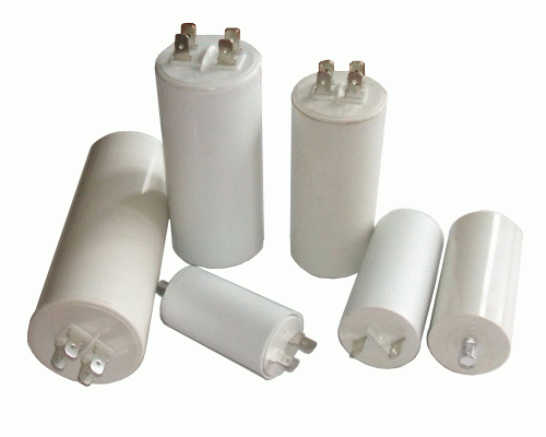
DC LinkThe DC link is the connection between these two circuits.  The DC link usually has a capacitor known as the DC link Capacitor.  This capacitor is connected in parallel between the positive and the negative conductors.  

The DC capacitor helps prevent the transients from the load side from going back to the distributor side.  It also serves to smoothen the pulses in the rectified DC.  


Capacitance Drift refers to the change in capacitance values over a period of time.  The value of a capacitor will change over the years.  This is because the property of the dielectric material and its ability to polarize or hold charge changes.  This is due to reasons such as age and temperature.  

A normal drift will be around 20% of the capacitance values.  The capacitance value can increase or decrease due to the capacitance drift.    If the capacitor is subject to temperatures beyond its working range or to temperature fluctuations, the value will drift.

The capacitance drift is irreversible.  Hence, capacitors should be selected keeping the capacitance drift in mind.  


Double Layer Capacitors are a type of electrolytic capacitors which have high storage density.  This enables them to have a high capacitance value.  The capacitance value of a double layer capacitor is of the order of Farads in comparison to normal capacitors which have micro farads and nano farads.

These capacitors have high rage of charging and discharging.  Double layer capacitors are also known as Supercapacitors or Ultra capacitors.

Double Layer Capacitors are used in a wide range of applications the Electric Automobile industry and in solar panels.

See Also


Self-healing is a feature in Film type capacitors.  Self healing is a process by which pin-hole defects in the dielectric film can be "healed" or rectified.  Thus, a dielectric free film is possible.

When a pinhole defect occurs in the di-electric film, there is a short circuit between the electrode layers on both sides. 

 This results in a heavy current flowing at the point of the fault.  this current causes a portion of the film layers to melt and vaporise.  This breaks the connection between the film layers and fault.

The energy expended in reparing the fault is very small of the order of micro-watts.  The process of self-healing is completed in about 10 microseconds.  


Frequency transducers are devices which generate an analog signal in accordance with the frequency to be measured. They are used in power systems and in electric equipment such as motors and generators to monitor the system frequency.
The output of the frequency transducer is usually connected to an automation device such as the PLC (Programmable Logic Controller) or a Distributed Control System (DCS).

Normal Power frequency transducers have a range between 0 and 100 or 120 Hz. Frequency transducers usually have analog outputs such as 4..20 mA, 0..20 mA and so on.

The output of these transducers can be configured. Modern transducers have three way isolation.


X  type capacitors are capacitors connected across two phases.  X type capacitors are used where damage to the capacitor will not result in a electric shock.  

Y Capacitors are used between a phase and the chassis (ground) of an equipment.  Y capacitors are used where the failure of the capacitor will lead to an electric shock if a proper ground connection is absent.  

X capacitors are classified into X1, X2 and X3. The classification of these capacitors is based on the peak voltage, the capacitor can withstand.  X1 capacitors can withstand 4000 volts.  X2 capacitors can withstand 2500 volts while X3 capacitors can withstand 1200 volts.

Y capacitors are classified into Y1, Y2 and Y3 and Y4.  Y1 capacitors can withstand 500 volts. Y2 capacitors can withstand 300 volts.  Y3 and Y4 capacitors can withstand 250 and 150 volts respectively.  

X capacitors are usually made of polyester, ceramic, polypropylene and paper.  Y capacitors are usually made of ceramic and paper.  


Prospective Short Circuit Current refers to the maximum short circuit current which can flow in a circuit in the event of a fault such as a short circuit or an earth fault.  It is the maximum current which can flow in the system.  
All the components of the system such as the cables, bus bars and the measuring and protection systems should be rated with reference to the Prospective Short circuit current. 

The interrupting devices such as fuses and circuit breakers should have an interrupting capacity greater than the prospective short circuit current.   
Prospective Short Circuit Current depends on the resistances and reactances of the system.  The prospective Short Circuit Current can  be obtained by a Fault Level Calculation Study of the system.


The Direct-On-Line or the DOL Starter is a method or starting motors where the supply voltage is directly applied to the motor terminals.  This results in heavy inrush currents and high starting torque.  

The heavy inrush currents may result in voltage dips in the system.  The high starting torque may result in damage to the coupling or to the connected load.

Thus, the Direct On Line Starter is used only in small motors such as those connected to pumps and blowers.


Star-Delta Starter is a very widely used type of motor starter. The Star Delta Starter is used to reduce the starting current and the starting torque. 


When the motor is started, there is a risk of heavy inrush currents if the line voltage is applied across the motor windings. This is because there is no back-emf to oppose the applied voltage. Thus, the three windings of the motor are initially connected in star. Thus the voltage across each individual winding is the phase voltage. 


 The current is thus reduced. This also reduces the torque.
Thus, heavy motors can be started with less disturbance to the power system. Once the motor has acquired sufficient speed, the winding connections are changed to Delta. By now, the sufficient back-emf would have developed to keep the currents within limits. 

The Delta connection enables the motor to develop higher torque. The motor windings are in delta during normal operation. Interlocks are provided to prevent short circuit during the changeover between the star and the delta connections. The star-delta starter can be used where the load is connected to the motor after start-up. This starter cannot be used for motor which have to be started along with the load as the initial starting torque through this method is zero.


Arc Suit is a protective equipment worn by personnel working in places where there is a risk of an arc flash.  Personnel working with HV equipment in switchyards and in HV panel rooms need to be properly protected against Arc Flash (See Article on Arc Flash).  

Arc Suit are made of fire and heat resistant materials.    These suits can protect the person from the immense heat and energy dissipated during an arc flash.  Arc suits are classified on the basis of kJ/sq.cm.  This refers to the maximum heat energy that the suit can withstand.  The appropriate suit should be selected based on the Arc Hazard Study which will give details of the maximum potential of an arc in a particular location.  


A coupling capacitor is a capacitor which is connected in series to a circuit.  The function of the coupling capacitor is to block DC and permit only AC to pass through.  Typical examples would be an audio circuit which requires only the amplified speech signal which is DC to be passed through.


The impedance offered by the capacitor is inversely proportional to the frequency.  Thus, the capacitor offers low impedance to the AC signal and high impedance to the DC signal.


Thermionic Emission refers to the emission of electrons in the presence of electric potential and temperature.  Thermionic emission occurs when a negative charged electrode is heated.  The heat energy agitates the atoms and the electrons leave the surface of the negatively charged material.
A Vacuum Tube

The rate of emission increases with the temperature.  Thermionic current occurs if an anode which is positive with respect to the cathode is placed near the cathode.


The Earthing point for the Aircraft is its aluminum frame.  

In any power system, Earthing or grounding is necessary so that power does not flow through a person who comes in contact with a live conductor.  Earthing also helps identify faults quickly.

On the ground, the ground serves as the earthing point providing a low resistance path for current which may leak on to the body of a equipment.  In Aircrafts and even automobiles, where contact with the ground is not possible, the frame itself serves as the grounding point. 


A Field Effect is a type of Transistor.  It is different from other type of the transistor, the Bipolar junction Transistor (PNP and NPN) in that there is only only junction.  Field Effect Transistors are unipolar transistors.  

A Field Effect Transistor consists of a Channel which conducts the Current.  One one end of the Channel is the Source and on the other is the Drain.  The Channel is made of N-type material.   Between the Source and the drain is a substrate of P-type material.    A terminal called the Gate is connected toe P-type material.   

The current from the source and the drain can be controlled by the voltage applied at the Gate.  This is the basic principle behind the Field Effect Transistor.When a negative voltage is applied at the P-type material, the electrons which are the majority charge carriers in the substrate are repelled, the depletion channel at the junction between the gate and the substrate increases, this decreasesthe available area for the electrons to pass through.  The current flow is thus reduced.  Thus, the current can be controlled by the gate voltage.

Reducing the negative gate voltage will cause the current flow to increase.  

Care should be taken that the gate voltage does not become positive with respect to the source.  This would reduce the depletion layer and cause current to flow between the substrate and the channel resulting in heating and failure of the Field Effect Transistor. 


If a signal shows zero value, there are two possibilities.  First, that the actual value of the process variable is zero, live zero.  A speed signal can show zero if the actual speed zero.  The signal can also be zero if the connection to the tachometer is broken, dead zero. 

Thus the analog signal which carries the process variable should indicate whether the zero is a genuine value of the process variable.  

This distinction can be made in analog signal formats such as the 4...20 mA.  In this format, the value is zero when the mA is 4.  This indicates that the circuit is healthy and that the reading is accurate.

If the value of the mA is 0, then it indicates a wire break.

Other examples of formats with live-zero function are the 1...5 V and 10...50 mV.


Pressure Relief Vents are provided in Electrolytic Capacitors to prevent explosions.  In electrolytic capacitors, hydrogen gas is released during operation.  Sometimes, due to reverse polarity or over voltage, the gas is released in excess.  This can result in high gas pressure.   

These vents rupture when the gas pressure inside the capacitor becomes excessive.  When the vent ruptures, gas at high temperature is released. Hence, adequate care should be taken to protect the eyes.


Intrinsic semiconductors are pure elements such as silicon and Germanium.  Intrinsic semiconductors have an equal number of holes and electrons.  At temperatures above 

absolute zero, some electrons get knocked out of the atoms.  Thus in an intrinsic semiconductor, the number of holes is equal to the number of electrons.

Intrinsic semiconductors have low conductivity.  When voltage is applied, a small current flows due to the holes and electrons.  As the the material is heated, the electrical conductivity of the the intrinsic semiconductor increases.  

Extrinsic Semiconductors are formed when an impurity is added to the intrinsic semiconductor.  In an extrinsic semiconductor, the number of holes is not equal to the number of electrons.  The number of these charge carriers depends on the type and extent of doping.  

When an extrinsic semiconductor is heated, the resistance decreases and the current increases.  The amount of current depends on the temperature and the extent of doping.


Arduino is an electronics platform which is used for electronic projects.  Arduino gets the input from the field sensors and switches and modifies the output based on a pre-written program in its memory. Arduino is the name of the company which owns the brand, the logo and the graphics design.

Arduino helps people with little programming skills to design robots, controllers, lighting and even art.  First developed in 2005 in Italy, Arduino has become immensely popular with hundreds of thousand Arduino boards being sold worldwide.

The arduino software can be downloaded for free at www.arduino.cc

Arduino boards

Arduino boards are predesigned boards with specific features, communication protocols and inputs/outputs.  There are USB based Board as well as boards with wireless nodes.   The Arduino board can be connected to the PC and programmed.  The inputs and outputs are connected to the board.  The program can be changed from the PC.  

Arduino projects and devices can also be interfaced with the PC so that the parameters which are measured can be viewed from the computer.

The Arduino programming software is Java based. 


Current signals are preferred over voltage signals as they are less prone to distortion due to interference and coupling.  Current Signals are also less prone to be affected to loop resistance.  

Any break in the circuit will be immediately noticed, if the live-zero provision is available.  


Power Conditioning refers to the process of improving the quality of AC power supply.  AC power supply is often affected by problems such as low or high voltages, harmonics, brownouts and spikes and transients. Such disturbances can damage loads connected to the supply.  

Power Conditioning Equipment eliminate these problems by filtering harmonics, maintaining voltage within limit (such as +/-1%). They also provide protection against noise.  

They also provide galvanic protection.  Power Conditioning Equipment work on a combination of technologies such as Harmonic Filters, Ferroresonant Transformers and Power Electronics to modify and smoothen the AC waveform.

Power Conditioning leads to improved life of components, protection from surges and spikes and and better performance and efficiency.


Doping in Semiconductors refers to the addition of donor atoms into the crystal structure of intrinsic semiconductors material to modify their conducting property.  In doping, an impurity or foreign atom is introduced into the lattice structure of a semiconductor material.  This makes free electrons or holes available in the lattice structure of the material.  

A semiconductor with an excess of free electrons is called an n-type semi-conductor while a semiconductor with an excess of holes is called a p-type semi-conductor.   N type semiconductors are made when the semi-conductor material is doped with a pentavalent impurity.  A pentavalent impurity is an impurity whose atom has 5 electrons in its outer most shell. Examples of pentavalent impurity are Antimony, Arsenic and Phosphorus.

A p-type semiconductor is obtained when the semiconductor material is doped with a trivalent impurity i.e. an element whose atom has three electrons in its outermost shell.  Examples of trivalent impurity are Boron, Aluminium and Gallium.  


A PNP transistor consists of two P-type materials with a N-type material sandwiched in between.  A NPN transistor consists of two N-type materials with a P-type material sandwiched in between.  

For a PNP transistor to conduct, the base which is made of N-type material has to be connected to the negative voltage.  The connection should look like this.  The transistor switches off when connected to the positive voltage.

In the NPN transistor, the base which is made of P-type material should be connected to the positive voltage.  The transistor will switch off when connected to the negative voltage.

PNP and NPN transistors can be identified by checking the polarity of the PN junction.  An PNP transistor has on PN junction and one NP junction.  Thus a simple check to identify the polarity of a diode can be used here.  Connect a multimeter positive to the base of the transistor and the multimeter negative to the emitter of the transistor.

If it shows low resistance the junction is in forward bias.  The transistor is a NPN transistor.  If it shows high resistance, the junction is in reverse bias and the transistor is PNP transistor.